Balcony Thermal Bridges: How to Read the Slab Edge
A balcony is an environmental junction as well as an outdoor room. Follow the load path, thermal layer and threshold to ask better questions before the slab edge is built.
By World Arch Journal ·


Project file
- FORMAT: International architectural design guide
- AUTHOR: World Arch Journal
- PUBLISHED: 18 October 2026
- ILLUSTRATIONS: 1 AI-assisted concept cover · 4 original explanatory diagrams
- SCOPE: Conceptual guidance · project-specific assessment required
A balcony thermal bridge begins where an outdoor structure crosses the building’s thermal envelope. At that junction, the plan’s clean outline conceals a three-dimensional problem: loads must reach the structure, rain must drain outward, and insulation and air seals must remain continuous. The balcony can look identical in an elevation while performing very differently at its connection.
The Passive House Institute’s balcony-connection database makes an important distinction: these are load-bearing components with thermal characteristics related to their structural capacity. A connector cannot be chosen from insulation thickness alone. This guide develops an original coordination method for architects, using conceptual drawings rather than a product ranking or a simulated building.
Start by asking a question that a rendering cannot answer: what crosses the insulation line, and how is that crossing assessed? The answer links early massing to the tender detail. The illustrations below explain that relationship; the cover is an AI-assisted concept visual, not a photograph of a documented project.
Read the edge before choosing a product
Imagine tracing a pencil around the insulated enclosure in section. At an ordinary wall, the line passes behind the cladding and around the window frame. At a projecting concrete balcony, it meets a slab extending outdoors. Adding insulation above and below that projection does not automatically restore the simple wall condition: the structural connection still needs evaluation.
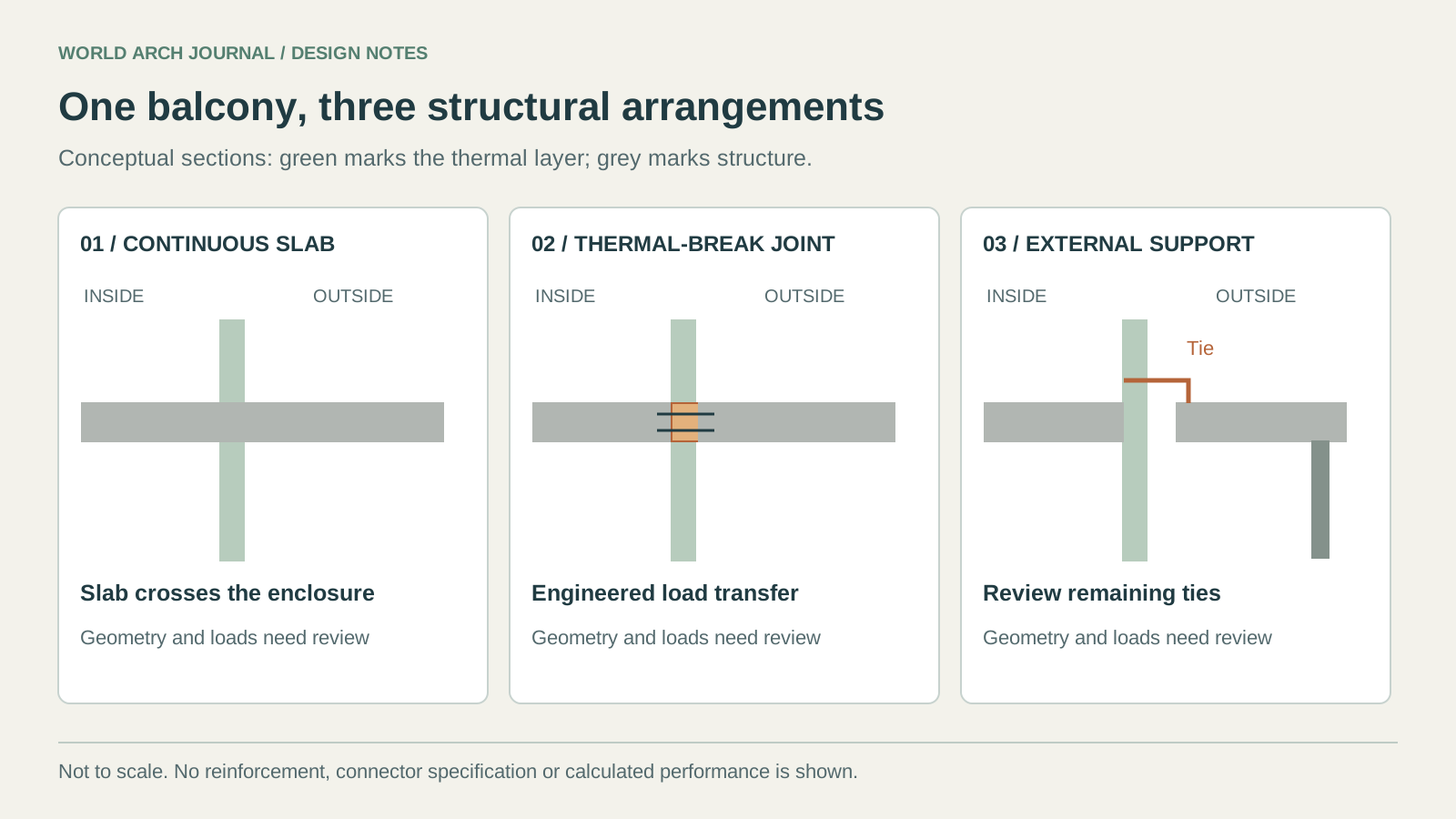
Our first drawing compares three architectural arrangements: a continuous projecting slab, a balcony connected through an engineered thermal break, and a separately supported external platform. These are different load-path decisions. They are not three interchangeable specifications, and the drawing deliberately assigns no performance ranking or numerical values.
A structural thermal break interrupts part of the conductive path while transferring the forces defined by the engineer. It still contains load-transferring elements. Calling it an absolute separation would be misleading. The connection’s dimensions, reinforcement or steel arrangement, adjacent construction and boundary conditions affect the result. A generic coloured strip on a section communicates intent, but does not establish compliance.
A separately supported balcony can move much of the supporting structure outside the insulated enclosure. Nevertheless, ties back to the building, thresholds and attachments remain potential bridges. It also introduces architectural questions: columns at ground level, foundations, differential movement, access, robustness and the relation between terraces and windows. There is no universal best arrangement independent of a real site.
For an existing building, begin with a survey rather than a presumed connector solution. Establish slab construction, condition, exposure, drainage and the existing enclosure. Opening-up investigations and structural assessment may change the feasible options. Compare the balcony intervention with the wider adaptive-reuse strategy, especially when retaining a sound structure has value beyond the junction itself.
Separate energy loss from surface temperature
Two questions are often collapsed into one: how much additional heat flows through the junction, and how cold can the interior surface become under the chosen conditions? These questions are related, but an energy figure alone does not describe every moisture or comfort concern at a floor edge.
Passipedia’s calculation guidance states that “surface temperatures can also be determined with the aid of heat flow simulations”. The short statement explains why a useful assessment should show more than a single headline value. Ask the analyst to identify the geometry, materials, reference dimensions, boundary conditions and the location of the critical interior surface.
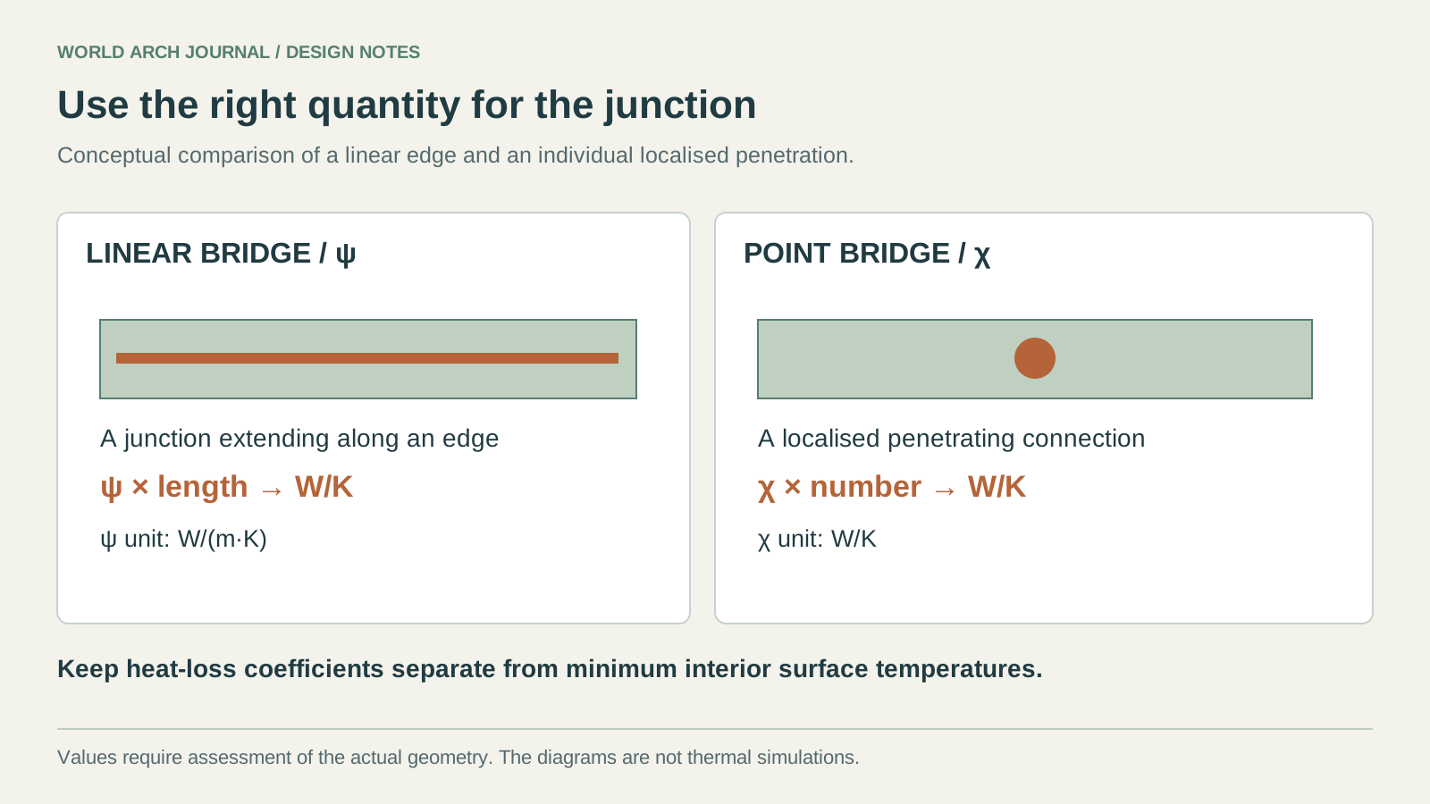
For linear junctions, the additional thermal transmittance is commonly expressed as psi, ψ, in W/(m·K). A localised point connection may require chi, χ, in W/K. IIBEC’s technical primer distinguishes these cases. Do not multiply a point value by a facade length, or compare a linear value with a material’s thermal conductivity. The units describe different things.
A deliberately hypothetical arithmetic check makes the distinction practical. Assume a linear junction has ψ = 0.30 W/(m·K) over 20 m. Its additional heat-loss coefficient is 6 W/K. At an assumed 20 K temperature difference, that term contributes 120 W. These invented inputs explain the calculation only: they are not a balcony benchmark, an annual energy prediction, a product result or an estimate of a room’s heating requirement.
Interior surface conditions also depend on climate, indoor temperature and humidity, operation and local geometry. A winter condensation assessment is not a universal answer for every hot-humid assembly. Set the project’s conditions first and have the appropriate specialist interpret the result. Coordinate this work with the whole-building energy strategy rather than using an isolated connector value as a building label.
Resolve the threshold as several continuous layers
The balcony door is where competing requirements become visible. A low, accessible threshold must coexist with water control, drainage, insulation, air sealing and movement. Solving one of these on a large-scale detail while leaving the others to separate drawings is a frequent coordination trap.
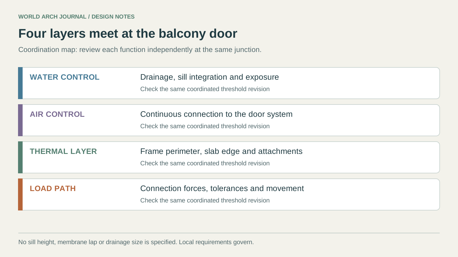
Use separate tracing colours for four questions. Where does bulk water go? Where is the airtight layer connected to the door assembly? Where does the thermal layer turn around the frame and slab edge? Which elements transfer load? A line that ends at another discipline’s annotation is an unresolved interface, not a completed junction.
Our threshold diagram is a relationship map, not a construction detail. It shows that water control, air control, thermal continuity and structural support need independent checks at the same location. It does not specify a sill height, membrane lap, drain size or proprietary support. Those decisions depend on the door system, exposure, accessibility requirements and the applicable local rules.
Draw the corner conditions as well as the typical section. Door jambs, balcony returns, balustrade posts and screen fixings may introduce localised penetrations or obstruct membrane installation. The balustrade belongs in the coordination model early enough that its fixings can be checked before waterproofing is complete.
Read the threshold with the adjacent rainscreen water-control strategy. A draining wall and a draining balcony cannot discharge into an unexamined interface. Likewise, a high-performance glazing specification does not compensate for a poorly integrated frame perimeter. Thermal, structural and water-control requirements must refer to the same assembly revision.
Compare options without an invented score
Before procurement, place the alternatives on one decision sheet. Use identical geometry and assessment assumptions where comparison is meaningful, and record differences where it is not. A smaller balcony with a different load case is not a fair proxy for a larger one simply because the connector names look similar.
| Arrangement | Question to resolve | Evidence to request |
|---|---|---|
| Continuous projecting slab | How does the slab crossing affect the whole junction? | Project geometry, heat-flow assessment and interior surface review |
| Engineered thermal-break connection | Does the assessed configuration match the required load transfer? | Structural design, applicable product documentation and junction calculation |
| Externally supported balcony | What ties, thresholds and movement interfaces remain? | Support strategy, attachment review and coordinated enclosure details |
Add buildability to the sheet. Who installs the connection? What tolerances can be accommodated? Which operations require inspection before concrete placement or closure? Where are membranes protected during later work? These questions may decide whether a carefully calculated junction survives the construction sequence.
Keep separate columns for thermal evidence, structural evidence and water-control review. A successful result in one column does not fill the others. If cost or programme drives a change, send the revised geometry back through every relevant check rather than accepting a substitution on the basis of a similar product description.
The useful outcome of this comparison is a recorded decision with named responsibilities. It may favour one arrangement for the current building while leaving another appropriate for a different project. An honest unresolved item is more valuable than a green tick unsupported by a drawing or calculation.
Carry the decision into construction and handover
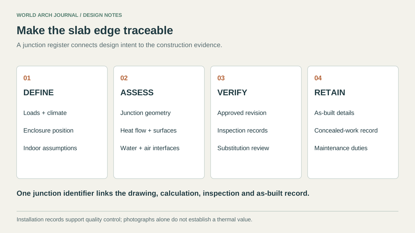
Create a junction register during design development. Give each balcony condition an identifier, its location and length or count, a reference detail, the calculation revision and the responsible reviewer. Include atypical corners and attachments. The register links the energy assessment to the actual drawing set and helps expose junctions that were missed when the facade changed.
At technical design, coordinate the architect, structural engineer, envelope specialist, energy assessor and supplier. Confirm that their documents describe the same geometry and material assumptions. Require a response when a detail is outside an assessed configuration; resemblance to a brochure illustration is not sufficient evidence.
- Before selection: define loads, climate, indoor conditions, enclosure position and accessibility needs.
- Before issue: review the thermal model, critical surface conditions, waterproofing, airtightness and movement together.
- Before closure: inspect the installation against the approved details and record relevant concealed work.
- At substitution: recheck every affected interface and assessment; do not carry results across automatically.
- At handover: retain the as-built details, inspection records and maintenance responsibilities with the building documentation.
Installation photographs are useful records, but they do not establish a thermal value. Infrared observations, if commissioned, also require suitable environmental conditions and competent interpretation; an attractive coloured image is not equivalent to the original calculation. Where a complaint arises, investigate moisture sources, ventilation, indoor conditions and construction as well as the suspected bridge.
The architectural opportunity is to make the balcony connection an early design choice. Its consequences reach the elevation, the ground plane, the door threshold and the future maintenance plan. A well-coordinated slab edge therefore begins with a readable section and ends with evidence that the same junction was actually built.
Continue exploring: the same junction thinking governs the terrace door, where water and thermal continuity meet — read the field note The Water Line: five decisions before a terrace door detail. For the facade surfaces that meet the balcony edge, compare the vein-cut travertine studies in the material library.
Frequently asked questions
Does a balcony thermal break eliminate every thermal bridge?
No. Load-transferring elements and adjacent interfaces still need assessment. Performance depends on the actual connection and surrounding assembly.
What is the difference between psi and chi?
Psi describes a linear thermal bridge in W/(m·K); chi describes a point thermal bridge in W/K. Neither is a material conductivity value.
Can a balcony on external columns avoid thermal bridges?
It can move much of the support outside the enclosure, but ties, thresholds and attachments still require review.
Are these diagrams construction details?
No. They are original conceptual explanations. Structural design, thermal modelling, water control and local requirements need project-specific review.
What is a thermal bridge?
A thermal bridge is a localised path where heat flows through a building envelope faster than through the surrounding construction — typically where structure, fixings or geometry interrupt the insulation layer. It raises heat loss and can cool interior surfaces enough to risk condensation and mould.
How can thermal bridging at a balcony be reduced?
Three architectural arrangements are compared in this guide: accept and assess a continuous projecting slab, connect the balcony through an engineered structural thermal break, or support the balcony externally so most structure stays outside the insulation. None is universally best — the choice depends on loads, geometry, threshold design and the assessed psi or chi values.
Evidence and source notes
- Passive House Institute — Balcony connections combine structural load transfer with thermal assessment.
- Passipedia — Heat-flow calculations can establish junction heat losses and surface temperatures.
- IIBEC — Distinguishes linear and point thermal bridges and their units.
Related architecture stories
- Solar Facades: 9 Decisions Before Putting Photovoltaics on Your Building
A solar facade is an envelope decision before it is an energy decision. Nine practical questions — from economics to orientation, maintenance and replacement — that decide whether photovoltaics earn their place on a building's skin.
- Bird-Safe Facade Design: A Practical Guide to Reducing Glass Collisions
Reflective and transparent glazing can conceal a collision hazard. This guide translates bird-friendly design research into a coordinated facade workflow for new buildings and retrofits—without treating one pattern or rule as universal.
- Low-E vs Triple Glazing vs Smart Glass: 8 Decisions That Matter
The best glazing is not the pane with the most layers or the darkest tint. It is the verified whole-window system that fits climate, orientation, comfort, daylight, controls and construction reality.
📌 Never miss a story — add World Arch Journal as your preferred source on Google: https://www.google.com/preferences/source?q=worldarchjournal.com